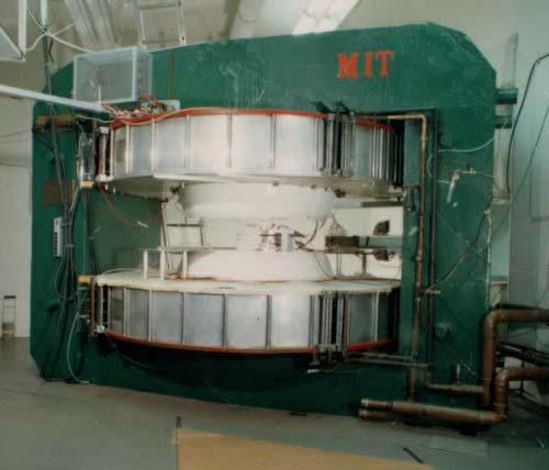
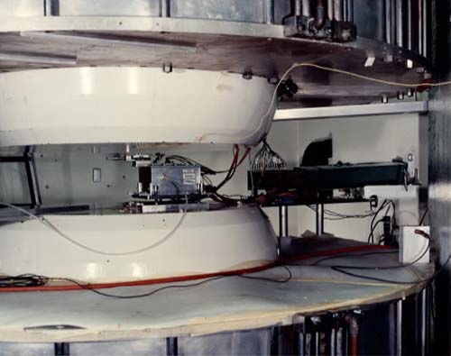
The test chamber is located in the center of the cyclotron magnet with wires horizontal (z coordinate) in the vertical (y) B field.
The beam of the UV laser is deflected via a movable mirror into the chamber volume. The beam of the N2 laser (337 nm) is sent from the former experimental cyclotron hall into the cyclotron containing the chamber. The beam is refocused by a f=1 m quartz lens to provide ~200 e-/cm of path of ionization in the chamber.
The chamber and the gas lines are first evacuated and then filled with the desired gas mixture thereafter continuing with a flow of one volume exchange per hour. The gas is premixed in a container tank by adding partial pressures. This method is accurate to <0.3% for binary mixtures. The high voltage on the wires is adjusted, for ~200 mV peak response to laser shots after amplification (24 mV/uA). The gas gain is ~4*104, which is far from saturation effects.
100 events (laser shots) are taken in each of the three mirror positions xl, x2, and x3, with x2-x1 = x3-x2 = 10.00+-0.01 mm setting error. Since x is parallel to E, the recorded times measure the parallel drift velocity component of interest by
v||(E,B) = (x3-x1)/(t3-t1),
which is consistent with (x2-x1)/(t2-t1) to within 0.6%. The distribution of arrival times from laser shots at the same x position has a 4 ns rms time jitter. This variation causes <0.15% error in the measured drift velocity.
The pad charges Qi, (i = 1,..., 20) are recorded from outputs of amplifiers calibrated to 0.5%. The y coordinate along the wire is derived from the weighted average
y = (·yiQi)/(·Qi)
The nonlinearity has been checked with micrometer controlled mirror movements and was found to be <200 um. The statistical fluctuation of each y measurement is 66 um in rms. The drift angle due to the Lorentz force depends on the gas as well as on the magnitude of E and B. and is determined by
alpha(E,B) = tan-1[(y3-y1)/(x3-x1)].
Note that both drift velocity and deflection angle are differential measurements, which eliminates the effect of different behavior of the amplification gap.
Because the differential measurements of positions 1-2 and 2-3
agreed well, the data sets past 1995 only use positions 1-2.
Data Adjustment
Because sea level is 760 torr and most US labs are at 24 degrees C or higher, the E fields have been
corrected for this.